

STK500 v1 and v2: the AVR programming protocol every embedded developer should understand
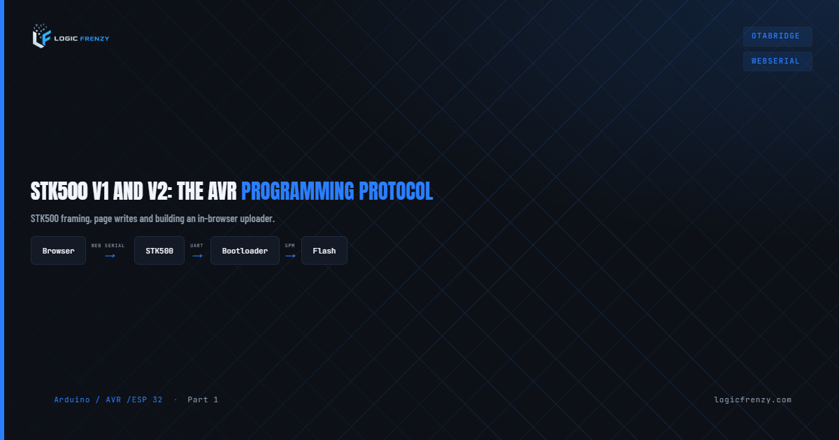
Every time you hit Upload in the Arduino IDE, something happens between your computer and the microcontroller that most tutorials completely ignore. A protocol negotiates, packets fly back and forth, fuses get read, flash gets written — and if anything goes wrong, you get a cryptic avrdude: stk500_recv(): programmer is not responding with no further explanation.
That protocol is STK500. Understanding it turns those errors from black boxes into diagnosable problems — and opens the door to uploading firmware directly from a browser, with no IDE, no drivers, and no avrdude installed.
What is STK500?
STK500 is Atmel’s (now Microchip’s) serial programming protocol for AVR microcontrollers. It was designed to run over a UART connection between a host computer and a programming device — originally the physical STK500 development board, later cloned into virtually every cheap AVR programmer on the market.
The protocol defines:
- How the host requests device information (signature bytes, fuse values, lock bits)
- How flash and EEPROM pages are loaded and written
- How the programmer enters and exits programming mode
- How errors are reported back to the host
avrdude — the tool behind Arduino’s upload process — implements STK500 on the host side. The programmer (your USBasp, Arduino-as-ISP, bootloader, or AVRISP mkII) implements it on the device side.
There are two versions: STK500 v1 and STK500 v2. They are not compatible with each other, and understanding which one your hardware uses is the first step to debugging upload failures.
STK500 v1
STK500 v1 is the original protocol, defined in Atmel application note AVR061. It is deliberately simple — small enough to fit inside 512 bytes of bootloader space on an AVR. That constraint shapes everything about its design: bare command bytes, no packet framing, no sequence numbers, no checksum. Just bytes and a single terminator.
It runs over UART. The host communicates through a USB-serial chip (ATmega16U2, CH340, CP2102) that converts USB packets to raw TX/RX serial bytes. The protocol never knows USB exists — it only sees the serial bytes arriving at the AVR’s UART peripheral.
Packet structure
Every command is a single byte, often followed by a small payload, terminated with STK_EOP (0x20):
CMD_BYTE [payload bytes...] STK_EOP (0x20)STK_EOP is sometimes written as Sync_CRC_EOP in documentation. The “CRC” in the name is a legacy artefact — Atmel originally planned a CRC field that was never implemented. There is no checksum in v1. The 0x20 (space character) is simply the terminator and nothing else.
The programmer responds with:
STK_INSYNC (0x14) [response bytes...] STK_OK (0x10)If the programmer is not in sync: STK_NOSYNC (0x15). If the command is unknown: STK_UNKNOWN (0x12).
Key commands
| Command byte | Name | Purpose |
|---|---|---|
0x30 | STK_GET_SYNC | Handshake — check programmer is alive |
0x41 | STK_GET_PARAMETER | Read firmware version, hardware version |
0x42 | STK_SET_PARAMETER | Set baud rate or reset delay |
0x45 | STK_ENTER_PROGMODE | Enter programming mode |
0x51 | STK_LEAVE_PROGMODE | Exit programming mode |
0x55 | STK_LOAD_ADDRESS | Set the word address for next read/write |
0x64 | STK_PROG_PAGE | Write a page of flash or EEPROM |
0x74 | STK_READ_PAGE | Read a page of flash or EEPROM |
0x75 | STK_READ_SIGN | Read the three signature bytes |
0x77 | STK_READ_FUSE | Read fuse bytes |
The sync dance
Before any programming can happen, host and programmer must synchronise. avrdude sends STK_GET_SYNC (0x30) followed by STK_EOP (0x20) and waits for STK_INSYNC (0x14) + STK_OK (0x10). It retries up to 10 times by default.
When debugging with -v -v, look for the raw sync attempt:
Sending : 0x30 0x20If you see this line repeated 10 times with no matching receive, the problem is hardware or timing — not software. The programmer is not answering at all.
Who uses STK500 v1
- Arduino bootloaders — Optiboot (used on Uno, Nano, Mini, and most 328P boards) speaks STK500 v1 over the UART. The USB-serial chip (e.g., ATmega16U2 or CH340) simply converts USB to the AVR’s TX/RX pins — the protocol never knows USB exists.
- Arduino-as-ISP — the ISP sketch loaded onto one Arduino to program another implements STK500 v1 at 19200 baud (not 115200)
- USBtinyISP — the cheap blue programmer uses a simplified STK500 v1 subset
When you select Arduino or avrisp as the programmer in the IDE, you’re using v1.
Why bootloaders use v1 and not v2: An STK500 v2 implementation requires building length-prefixed packets with checksums and managing sequence numbers. That code does not fit in 512 bytes. v1’s flat structure is compact enough that Optiboot fits entirely within the smallest AVR bootloader section and still leaves room for a watchdog reset.
Optiboot and the reset timing problem
Optiboot’s STK500 v1 implementation has a watchdog: it waits approximately 500 ms after reset for a STK_GET_SYNC packet. If none arrives, it jumps to the application.
This is why the Arduino IDE automatically toggles the DTR line on the USB-serial chip — it triggers a reset on the AVR, then immediately starts sending sync packets before the window closes.
If your USB-serial adapter doesn’t support DTR, or DTR is not wired to the AVR reset pin, uploads will fail consistently. The sketch starts running before avrdude even begins talking.
Baud rate note: Optiboot on 16 MHz boards uses 115200. On 8 MHz boards (Pro Mini 3.3V, LilyPad) it uses 57600. ArduinoISP uses 19200. The “not in sync” error is often just a baud rate mismatch — always check the board’s boards.txt entry to confirm.
STK500 v2
STK500 v2 is a complete redesign, described in Atmel application note AVR069. It was introduced with updated firmware for the physical STK500 board and is the protocol used by bench programmers where code size is not a constraint.
The goals were:
- Structured, length-prefixed packets with a checksum
- Sequence numbers to detect dropped or duplicated packets
- Support for 32-bit address spaces (required for AVRs with more than 64 KB flash)
- Support for PDI and JTAG in addition to ISP
Packet structure
MESSAGE_START   (0x1B)
SEQUENCE_NUMBER (1 byte, wraps 0x00–0xFF)
MESSAGE_SIZE_HIGH (1 byte)
MESSAGE_SIZE_LOW  (1 byte)
TOKEN           (0x0E)
MESSAGE_BODY    (MESSAGE_SIZE bytes)
CHECKSUM        (1 byte)
The checksum is the XOR of every byte in the packet from MESSAGE_START up to but not including the checksum byte itself. The receiver computes the XOR of the received bytes and compares it to the trailing checksum; if they match, the packet is valid.
The host increments the sequence number with each command. The programmer echoes the same number in its response, letting the host detect dropped or out-of-order packets — something v1 cannot do at all.
Response structure
Responses follow the same packet format. The first byte of MESSAGE_BODY is always the command being answered, followed by a status byte:
CMD_BYTE STATUS [response data...]| Status value | Meaning |
|---|---|
0x00 | STATUS_CMD_OK |
0x01 | STATUS_CMD_TOUT — command timed out |
0x02 | STATUS_RDY_BSY_TOUT — device busy timeout |
0x03 | STATUS_SET_PARAM_MISSING — required parameter not set |
0x80 | STATUS_CMD_FAILED |
0x81 | STATUS_CMD_UNKNOWN |
Key commands
| Command | Name | Purpose |
|---|---|---|
0x01 | CMD_SIGN_ON | Identify programmer, get firmware string |
0x02 | CMD_SET_PARAMETER | Set programming parameters |
0x03 | CMD_GET_PARAMETER | Read programmer parameters |
0x10 | CMD_ENTER_PROGMODE_ISP | Enter ISP programming mode |
0x11 | CMD_LEAVE_PROGMODE_ISP | Leave ISP programming mode |
0x13 | CMD_CHIP_ERASE_ISP | Full chip erase |
0x14 | CMD_PROGRAM_FLASH_ISP | Write a flash page |
0x15 | CMD_READ_FLASH_ISP | Read flash |
0x16 | CMD_PROGRAM_EEPROM_ISP | Write EEPROM |
0x17 | CMD_READ_EEPROM_ISP | Read EEPROM |
0x1A | CMD_PROGRAM_FUSE_ISP | Write fuse bytes |
0x1B | CMD_READ_FUSE_ISP | Read fuse bytes |
0x1C | CMD_PROGRAM_LOCK_ISP | Write lock bits |
0x1D | CMD_READ_LOCK_ISP | Read lock bits |
0x1F | CMD_READ_SIGNATURE_ISP | Read device signature |
The CMD_SIGN_ON handshake
Unlike v1’s bare sync byte, v2 opens with a full structured packet:
1B 01 00 01 0E 01 13Breaking that down:
1B— MESSAGE_START01— sequence number 100 01— body is 1 byte long0E— TOKEN01— CMD_SIGN_ON13— checksum (XOR of all previous bytes)
The programmer responds with a packet whose body contains 01 (CMD_SIGN_ON echoed), 00 (STATUS_CMD_OK), a length byte, and an ASCII programmer name like AVRISP_MK2 or STK500_2.
Port selection: USB HID vs serial
This is a common source of confusion. STK500 v2 runs over two different physical connections depending on the programmer:
AVRISP mkII — uses libusb/HID. Use -P usb:
avrdude -c avrispmkII -p atmega2560 -P usbPhysical STK500 board — connects via a serial port. Use the port name:
avrdude -c stk500v2 -p atmega2560 -P /dev/ttyUSB0Using -P usb with a serial device (or vice versa) will fail immediately. Check your programmer’s datasheet or the avrdude.conf entry to confirm which transport it uses.
Who uses STK500 v2
- AVRISP mkII — Atmel’s official bench programmer
- Physical STK500 board (firmware v2+) — the original hardware, updated
- STK600 — Atmel’s newer development board
- JTAGICE mkII (in ISP mode) — also speaks v2
When you select AVRISP mkII in the Arduino IDE, you’re using v2.
STK500 v2 and the Arduino Mega
The Arduino Mega 2560 is the most common board where developers encounter STK500 v2 directly, because the ATmega2560 has 256 KB of flash — far beyond the 64 KB v1 address space.
The Mega’s bootloader (STK500v2 compatible, shipped as stk500boot_v2_mega2560.hex) speaks STK500 v2 over the USB-serial connection from the ATmega16U2. This is why the Mega’s programmer type in boards.txt is stk500v2, not arduino:
mega.upload.protocol=wiring
mega.upload.maximum_size=253952
mega.upload.speed=115200
mega.upload.tool=avrdude
mega.bootloader.tool=avrdude
mega.bootloader.low_fuses=0xFF
mega.bootloader.high_fuses=0xD8
mega.bootloader.extended_fuses=0xFD
The wiring protocol is avrdude’s alias for STK500 v2 with some Mega-specific timing adjustments.
Key difference when working with the Mega:
- Page size is 256 bytes (vs 128 bytes on the 328P) — each
CMD_PROGRAM_FLASH_ISPpacket is larger - Addresses are 3 bytes wide — v2’s 32-bit address field is actually needed here
- Upload takes longer because of the larger flash and bigger pages
If you’re using an external ISP programmer with the Mega (burning bootloader or programming directly), always check the ISP clock speed. The ATmega2560 running from an 16 MHz crystal supports ISP up to 4 MHz, but if you’re restoring a bricked Mega where fuses were wiped, it may be running at 1 MHz internal — drop to -B 125kHz first.
v1 vs v2: a direct comparison
| Property | STK500 v1 | STK500 v2 |
|---|---|---|
| Packet framing | Bare bytes + 0x20 terminator | Length-prefixed + XOR checksum |
| Sequence numbers | None | Yes (1 byte, wraps 0xFF→0x00) |
| Error detection | None | XOR checksum per packet |
| Max flash address | 16-bit word (64 KB) | 32-bit (supports >64 KB) |
| Baud rate | Fixed per bootloader (57600/115200) | Negotiated |
| Bootloader use | Yes — fits in 512 bytes | Not practical — too much code |
| Hardware programmer | USBtinyISP, Arduino-as-ISP | AVRISP mkII, STK600 |
| avrdude type | arduino, avrisp, usbtiny | avrispmkII, stk500v2, wiring |
| Physical transport | UART (via USB-serial) | UART or USB HID |
| Boards | Uno, Nano, Mini, Pro Mini | Mega 2560, Mega ADK |
| Introduced | ~2000 | ~2003 |
How avrdude chooses the protocol
avrdude selects the protocol based on the -c programmer argument:
# STK500 v1 — Uno/Nano via bootloader
avrdude -c arduino -p atmega328p -P /dev/ttyUSB0 -b 115200

# STK500 v2 — Mega 2560 via bootloader
avrdude -c wiring -p atmega2560 -P /dev/ttyUSB0 -b 115200

# STK500 v2 — AVRISP mkII via USB HID
avrdude -c avrispmkII -p atmega2560 -P usb

# STK500 v2 — physical STK500 board via serial port
avrdude -c stk500v2 -p atmega2560 -P /dev/ttyUSB0
Enable double-verbose logging to see every packet:
avrdude -c arduino -p atmega328p -P /dev/ttyUSB0 -b 115200 -v -vLook for Sending : lines. If you see:
Sending : 0x30 0x20repeated 10 times with no receive, the problem is hardware or timing — not avrdude. The programmer is simply not answering.
Common errors and what they actually mean
stk500_recv(): programmer is not responding
The host sent a sync packet and got nothing back within the timeout window.
Diagnose:
- Is the port correct? Run
ls /dev/tty*(Linux/Mac) or check Device Manager (Windows) - Is the baud rate correct? Optiboot 16 MHz = 115200. Optiboot 8 MHz = 57600. ArduinoISP = 19200.
- Is DTR connected? The CH340/CP2102 DTR pin must reach the AVR reset pin.
- Did the bootloader time out? Press reset on the board the instant avrdude starts.
stk500_getsync() attempt N of 10: not in sync: resp=0xXX
The programmer responded, but not with STK_INSYNC (0x14). The 0xXX is the first byte it sent instead.
resp=0x00— The bootloader window has closed. The application is now running. If the application sends no serial output, the UART line sits idle and the host sees0x00. Press reset and retry immediately, or fix the DTR wiring.resp=0x15— Programmer answered withSTK_NOSYNC— it received something but considers itself out of sync. Retry usually fixes this.- Any printable ASCII — the sketch is running and sending serial output. The bootloader already timed out before avrdude connected.
avrdude: stk500v2_ReceiveMessage(): timeout
The v2 programmer did not respond to a packet. Common causes:
- USB connection issue with the AVRISP mkII — try a different cable or port
- Target device not powered — if the target has no VCC, ISP lines float and the programmer cannot communicate. Ensure the target’s VCC is connected, not just the programmer’s VCC output pin.
- ISP clock speed too high for the target (see “ISP clock trap” below)
avrdude: stk500v2_command(): failed to set SCK
The programmer acknowledged the command but failed to set the ISP clock. Almost always means the target is not responding on the ISP lines.
Check target power first. If VCC is not connected to the target, the ISP lines will float at an indeterminate voltage. The programmer cannot drive them correctly and fails immediately. Connect VCC to the target’s VCC pin (not just the programmer’s output).
Then verify MISO/MOSI/SCK/RESET wiring, and check voltage levels: a 5V programmer talking to a 3.3V target will often produce unreliable ISP communication because the logic high threshold on the 3.3V device is typically 0.7×VCC = 2.31V — which a 5V programmer can drive — but the MISO line from the 3.3V device may not register as a valid high on a 5V programmer. Use a level shifter or a programmer that supports 3.3V IO.
Expected signature for ATmega328P is 1E 95 0F
Wrong device selected, or the chip is dead, not powered, or not connected. Read the actual returned signature from the verbose output to identify what’s on the bus.
The ISP clock trap
This is the single most common reason an AVRISP mkII fails on a brand-new AVR.
Fresh ATmega chips ship with the internal 8 MHz RC oscillator selected and a clock divider fuse (CKDIV8) enabled — running at 1 MHz. The rule is that the ISP clock must be no more than 1/4 of the target clock.
At 1 MHz target clock, maximum ISP clock = 250 kHz.
The default ISP clock in avrdude is 1 MHz. Trying to program at 1 MHz ISP into a 1 MHz target means the chip misses bits, ISP communication is garbled, and you get timeout errors.
Fix with the -B flag (bit clock period in microseconds, or a frequency string):
# 125 kHz ISP — safe for any target running at 500 kHz or faster
avrdude -c avrispmkII -p atmega328p -P usb -B 125kHz

# Equivalent using period: 8 µs = 125 kHz
avrdude -c avrispmkII -p atmega328p -P usb -B 8
Once you’ve set the fuses to select an external crystal or disable CKDIV8, speed the ISP clock back up.
Reading and writing fuses with avrdude
# Read all fuses (Uno via bootloader)
avrdude -c arduino -p atmega328p -P /dev/ttyUSB0 -b 115200 \
  -U lfuse:r:-:h -U hfuse:r:-:h -U efuse:r:-:h

# Write fuses (Uno defaults — 16 MHz crystal, 512-word bootloader)
avrdude -c avrispmkII -p atmega328p -P usb \
  -U lfuse:w:0xFF:m \
  -U hfuse:w:0xDE:m \
  -U efuse:w:0x05:m
Warning: Incorrect fuse values — especially disabling the reset pin or selecting an unavailable clock source — make the chip appear bricked. It is not bricked, but recovery requires a high-voltage programmer. Always calculate fuses with a verified tool (engbedded.com AVR Fuse Calculator) and double-check before writing.
Burn bootloader: what actually happens
When you select Tools → Burn Bootloader in the Arduino IDE, it runs two avrdude commands in sequence:
- Fuse write — sets lfuse, hfuse, efuse to the values in
boards.txtfor that board - Flash write — writes the bootloader hex to the bootloader section at the top of flash
The programmer used for this must be an ISP programmer — not the bootloader itself. After the bootloader is burned, all subsequent uploads from the IDE use the bootloader (STK500 v1 for 328P, STK500 v2 for 2560).
Practical setup: Arduino-as-ISP
If you don’t own a dedicated programmer, any Arduino can become one using the built-in ArduinoISP sketch. It implements STK500 v1 at 19200 baud.
Wiring:
| ISP Arduino (programmer) | Target |
|---|---|
| Pin 10 | RESET |
| Pin 11 | MOSI |
| Pin 12 | MISO |
| Pin 13 | SCK |
| 5V | VCC |
| GND | GND |
Put a 10 µF capacitor between RESET and GND on the programmer Arduino — this prevents it from resetting when avrdude opens the serial port. Note: Leonardo and Micro handle DTR differently and require a 120 Ω resistor on the RESET line instead. Check the specific guide for your board.
avrdude -c avrisp -p atmega328p -P /dev/ttyUSB0 -b 19200 \
  -U flash:w:your_sketch.hex:i
Uploading firmware from the browser
This is where STK500 becomes genuinely interesting in 2026. The Web Serial API — supported in Chrome, Edge, and Opera — gives a web page direct access to serial ports. Combined with a JavaScript implementation of the STK500 protocol, you can upload firmware to an Arduino directly from a browser with no avrdude, no IDE, and no native software installed.
How it works
The Web Serial API exposes:
const port = await navigator.serial.requestPort();
await port.open({ baudRate: 115200 });

const writer = port.writable.getWriter();
const reader = port.readable.getReader();
From there, you implement the STK500 state machine in JavaScript — send sync packets, negotiate, load addresses, write pages, verify. The browser becomes avrdude.
STK500 v1 in JavaScript (Uno/Nano)
A minimal v1 flash upload:
const STK_OK      = 0x10;
const STK_INSYNC  = 0x14;
const STK_EOP     = 0x20;
const STK_GET_SYNC = 0x30;
const STK_ENTER_PROGMODE = 0x45;
const STK_LOAD_ADDRESS   = 0x55;
const STK_PROG_PAGE      = 0x64;
const STK_LEAVE_PROGMODE = 0x51;

async function sendCommand(writer, reader, cmd) {
  await writer.write(new Uint8Array([...cmd, STK_EOP]));
  // read STK_INSYNC + response + STK_OK
  return await readResponse(reader);
}

async function sync(writer, reader) {
  for (let i = 0; i < 10; i++) {
    await writer.write(new Uint8Array([STK_GET_SYNC, STK_EOP]));
    const resp = await readWithTimeout(reader, 200);
    if (resp?.[0] === STK_INSYNC && resp?.[1] === STK_OK) return true;
  }
  throw new Error('Programmer not responding');
}

async function uploadHex(port, hexData) {
  const writer = port.writable.getWriter();
  const reader = port.readable.getReader();

  // Toggle DTR to reset the board
  await port.setSignals({ dataTerminalReady: false });
  await delay(100);
  await port.setSignals({ dataTerminalReady: true });
  await delay(100);

  await sync(writer, reader);
  await sendCommand(writer, reader, [STK_ENTER_PROGMODE]);

  const pages = parseHexToPages(hexData, 128); // 128-byte pages for 328P

  for (const { address, data } of pages) {
    // Load word address (address / 2)
    const wordAddr = address >> 1;
    await sendCommand(writer, reader, [
      STK_LOAD_ADDRESS,
      wordAddr & 0xFF,
      (wordAddr >> 8) & 0xFF,
    ]);

    // Write page
    await sendCommand(writer, reader, [
      STK_PROG_PAGE,
      0x00, data.length,  // size high, low
      0x46,               // 'F' = flash
      ...data,
    ]);
  }

  await sendCommand(writer, reader, [STK_LEAVE_PROGMODE]);

  writer.releaseLock();
  reader.cancel();
}
STK500 v2 in JavaScript (Mega 2560)
v2 requires building proper framed packets. A packet builder:
function buildV2Packet(sequenceNum, body) {
  const size = body.length;
  const packet = [
    0x1B,                    // MESSAGE_START
    sequenceNum & 0xFF,      // SEQUENCE_NUMBER
    (size >> 8) & 0xFF,      // MESSAGE_SIZE_HIGH
    size & 0xFF,             // MESSAGE_SIZE_LOW
    0x0E,                    // TOKEN
    ...body,
  ];
  // Checksum: XOR of all bytes
  const checksum = packet.reduce((acc, b) => acc ^ b, 0);
  return new Uint8Array([...packet, checksum]);
}

let seqNum = 1;

async function sendV2Command(writer, reader, body) {
  const packet = buildV2Packet(seqNum++, body);
  await writer.write(packet);
  return await readV2Response(reader);
}

// Sign on
async function signOn(writer, reader) {
  const resp = await sendV2Command(writer, reader, [0x01]); // CMD_SIGN_ON
  if (resp.status !== 0x00) throw new Error('Sign-on failed');
  return resp.programmerName; // e.g. "AVRISP_MK2"
}
What this enables
- In-browser firmware update pages — ship a product with a web page at
device.local/update. User clicks “Upload”, selects a.hexfile, the page flashes the device. Zero software to install. - OTA via USB — for devices that physically connect to a computer but have no WiFi. Especially useful in factory programming stations where IT won’t install native tools.
- Educational tools — platforms like the LogicFrenzy simulator can load and flash real hardware in the same browser tab as the tutorial.
- Field service tools — a technician opens a URL on a tablet and flashes firmware to a connected device.
Browser compatibility
| Browser | Web Serial API |
|---|---|
| Chrome 89+ | ✅ Full support |
| Edge 89+ | ✅ Full support |
| Opera 75+ | ✅ Full support |
| Firefox | ❌ Not supported |
| Safari | ❌ Not supported |
The API requires a user gesture (button click) to request port access — it cannot silently open a port. HTTPS is required in production (localhost works without it).
Existing implementations
You don’t have to implement the protocol from scratch. Several open-source libraries already do it:
- avrgirl-arduino (Node.js, also works in browser via webpack) — wraps STK500 v1 and v2
- arduino-create-agent — Arduino’s own browser-to-serial bridge, though it uses a native agent
- web-stk500 — a lightweight pure-JS STK500 v1 implementation for browser use
For production use, avrgirl-arduino is the most battle-tested starting point.
Debugging with a logic analyser
If you’re still stuck after trying the above, put a logic analyser on the TX/RX lines and decode the UART traffic.
Cheap logic analysers (Saleae clones, Cypress-based) work fine at 115200. Look for:
- Are packets being sent? If TX is flat, the software isn’t opening the port correctly.
- Is the baud rate correct? Zoom in on a start bit and measure the bit period. At 115200, each bit is ~8.68 µs.
- Is the programmer responding? TX activity with no RX means the programmer isn’t answering.
- What is the programmer sending? If RX is active but the host rejects it, decode the bytes and compare to STK500 expected responses.
- Check voltage levels. A 5V programmer connected to a 3.3V target may have MISO signal levels too low to register reliably. The 3.3V device drives MISO high at 3.3V, which a 5V programmer may interpret correctly — but inconsistently. Use a level shifter for reliable ISP at mixed voltages.
Summary
STK500 v1 and v2 are both serial ISP programming protocols, but they serve different needs:
- v1 is simple, tiny, and fits in a bootloader. Used everywhere from Optiboot to ArduinoISP. Limited to 64 KB flash. Baud rate varies by board — always check.
- v2 is structured, checksummed, and supports the full 32-bit address space. Required for the ATmega2560 (Arduino Mega) and other large-flash devices. Used by bench programmers and the Mega’s own bootloader.
Understanding the protocol means understanding the errors — the sync dance, the bootloader window, the ISP clock constraint, the power and voltage issues. Most upload failures come down to one of five things: wrong port, wrong baud rate, missing DTR reset, ISP clock too fast, or target not powered.
And with the Web Serial API, both protocols are now fully implementable in a browser. The same handshake that happens in avrdude can happen in a <script> tag — opening firmware update flows that require nothing more than Chrome and a USB cable.
Related posts
Comments
Enjoyed this tutorial?
Get new ESP32, Arduino, and industrial IoT tutorials straight to your inbox — no spam, unsubscribe anytime.